Writing VTK XML files in C++
I visualize the output of my simulations using either LLNL’s Visit or Kitware’s ParaView. These tools are wonderful for dealing with large datasets and can read a huge variety of file formats. In particular, they are good for remote and visualization.
One of the formats that both these tools can understand is the VTK XML format. The advantage of this format is its simplicity and that makes it suitable for small research codes.
Note: If your code is running on large modern HPC machines, you should consider formats that are more efficient for I/O and remote visualization.
In this blog post I’ll describe how I write data from my particle-based simulations into VTK format output files. If the files are small, I use ASCII for readability but for large simulations I write out VTK XML files containing binary data.
The data
The data produced by the particle simulation codes typically has two components:
- A grid that describes the boundary of the computational domain and the partitioning of the domain into pieces that are sent to various processors during the computation process, and
- A set of particles that contain position, geometry, and physical state data.
Each of these datasets changes with time; so they also contain a timestamp. A set of files is produced at each timestep in the simulation where the user feels that there is a need to output results. The process of creating appropriately named files is routine and won’t be described in this post.
Installing VTK and setting up Cmake
In Ubuntu 16.04, installing VTK (a slightly older version, 5.10), is straightforward. I haven’t tried more recent versions, but the API hasn’t changed much. Most HPC systems also have VTK installed by default because of its wide use. Installation just needs
sudo apt-get install libvtk5-dev
To be able to build your code with VTK support, edit the root CMakeLists.txt file and add
  find_package(VTK 5.10 REQUIRED)
  include_directories(${VTK_INCLUDE_DIRS})
and for linking the executable, add
  target_link_libraries(your_executable
    YOUR_LIB
    ${VTK_LIBRARIES}
  )
Writing grid data
We write the grid using an unstructured grid writer (because the grid may not be regular) but stick to hexahedral elements in this example.
#include <vtkXMLUnstructuredGrid.h>
#include <vtkXMLUnstructuredGridWriter.h>
#include <vtkSmartPointer.h>
#include <vtkPoints.h>
using vtkPointsP                    = vtkSmartPointer<vtkPoints>;
using vtkUnstructuredGridP          = vtkSmartPointer<vtkUnstructuredGrid>;
using vtkHexahedronP                = vtkSmartPointer<vtkHexahedron>;
using vtkXMLUnstructuredGridWriterP = vtkSmartPointer<vtkXMLUnstructuredGridWriter>;
using Node    = std::vector<double>;
using Element = std::vector<int>;
void
OutputVTK::writeGrid(double time,
                     const BoxArray& grid,
                     std::ostringstream& fileName)
{
  // Create a writer
  auto writer = vtkXMLUnstructuredGridWriterP::New();
  // Append the default extension to the file name
  fileName << "." << writer->GetDefaultFileExtension();
  writer->SetFileName((fileName.str()).c_str());
  // Create a pointer to a VTK Unstructured Grid data set
  auto dataSet = vtkUnstructuredGridP::New();
  // Set up pointer to point data
  auto pts = vtkPointsP::New();
  // Count the total number of points to be saved
  int num_pts = grid.getNumberOfPoints(); // Implementation is user-dependent
  pts->SetNumberOfPoints(num_pts);
  // Add the time
  addTimeToVTKDataSet(time, dataSet);
  // Get the nodes and elements that are used to describe the grid
  std::vector<Node>    nodes = grid.getNodes();       // Implementation is user-dependent
  std::vector<Element> elements = grid.getElements(); // Implementation is user-dependent
  // Add the processor boundaries to the unstructured grid cell data
  addElementsToVTKDataSet(nodes, elements, pts, dataSet);
  // Set the points
  dataSet->SetPoints(pts);
  // Remove unused memory
  dataSet->Squeeze();
  // Write the data
  writer->SetInput(dataSet);
  writer->SetDataModeToAscii();
  writer->Write();
}
We will discuss the implementation of addTimeToVTKDataSet and addElementsToVTKDataSet next. Note the SetDataModeToAscii() function near the end. We can switch to binary output by just changing this call to SetDataModeToBinary().
Adding time to the data set
To add a time stamp to each data set, we use the following
void
OutputVTK::addTimeToVTKDataSet(double time,
                               vtkUnstructuredGridP& dataSet)
{
  auto array = vtkDoubleArrayP::New();
  array->SetName("TIME");
  array->SetNumberOfTuples(1);
  array->SetTuple1(0, time);
  dataSet->GetFieldData()->AddArray(array);
}
Adding elements to the data set
Finally, we will add the grid elements to the dataset using the addElementsToVTKDataSet function below.
void
OutputVTK::addElementsToVTKDataSet(const std::vector<Node>& nodes,
                                   const std::vector<Element>& elements,
                                   vtkPointsP& pts,
                                   vtkUnstructuredGridP& dataSet)
{
  // Set the coordinates of the nodes
  int id = 0;
  for (const auto& node : nodes) {
    pts->SetPoint(id, node[0], node[1], node[2]);
    ++id;
  }
  // Set the element connectivities
  auto hex = vtkHexahedronP::New();  // Assuming hex elements
  for (const auto& element : elements) {
    // Get node ids and assign them to a hex element (ids start from 1)
    int nodeNum = 0;
    for (const auto& id : element) {
      hex->GetPointIds()->SetId(nodeNum, id - 1);
      ++nodeNum;
    }
    dataSet->InsertNextCell(hex->GetCellType(), hex->GetPointIds());
  }
}
The output file
The output file produced by this approach has the extension .vtu and the format below.
<?xml version="1.0"?>
<VTKFile type="UnstructuredGrid" version="0.1" byte_order="LittleEndian" compressor="vtkZLibDataCompressor">
<UnstructuredGrid>
<FieldData>
<DataArray type="Float64" Name="TIME" NumberOfTuples="1" format="ascii" RangeMin="0" RangeMax="0">
0
</DataArray>
</FieldData>
<Piece NumberOfPoints="18" NumberOfCells="4">
<PointData>
</PointData>
<CellData>
</CellData>
<Points>
<DataArray type="Float32" Name="Points" NumberOfComponents="3" format="ascii" RangeMin="0" RangeMax="101.56425869">
0 -1 0 0 -1 17.728469849
0 0 0 0 0 17.728469849
0 1 0 0 1 17.728469849
50 -1 0 50 -1 17.728469849
50 0 0 50 0 17.728469849
50 1 0 50 1 17.728469849
100 -1 0 100 -1 17.728469849
100 0 0 100 0 17.728469849
100 1 0 100 1 17.728469849
</DataArray>
</Points>
<Cells>
<DataArray type="Int64" Name="connectivity" format="ascii" RangeMin="0" RangeMax="17">
6 8 2 0 7 9
3 1 8 10 4 2
9 11 5 3 12 14
8 6 13 15 9 7
14 16 10 8 15 17
11 9
</DataArray>
<DataArray type="Int64" Name="offsets" format="ascii" RangeMin="8" RangeMax="32">
8 16 24 32
</DataArray>
<DataArray type="UInt8" Name="types" format="ascii" RangeMin="12" RangeMax="12">
12 12 12 12
</DataArray>
</Cells>
</Piece>
</UnstructuredGrid>
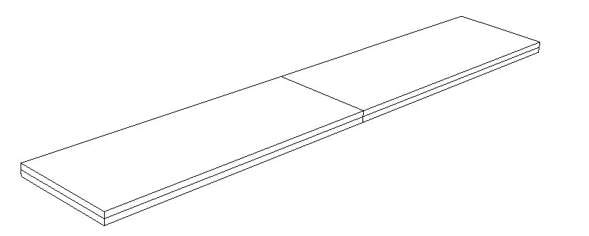
</VTKFile>The data can be easily read into Visit and the resulting plot can be seen below.
Remarks
Writing your data to files in VTK format is straightforward and reading them in Visit or ParaView is also quite simple. I prefer these tools to TecPlot, mainly because I can write plugins quite easily.
In the next post, I will discuss how you can save your particle data in VTK binary format.
If you have questions/comments/corrections, please contact banerjee at parresianz dot com dot zen (without the dot zen).